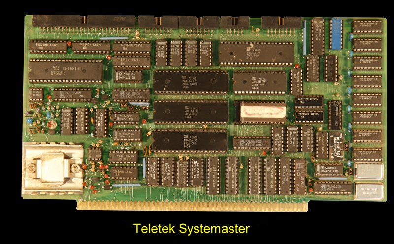
Teletek - Systemaster
This SBC could be used in a single user system or as a master in a
multi-processor network.

The Systemaster
was a complete S-100 system on one board. It incorporated a
CPU, DMA, floppy disk controller, and all the I/O and memory normally
required in a system.
CENTRAL PROCESSOR.
A 4MHz Z8OA microprocessor was utilized as the CPU. The Z80A provided the
capability to support many sophisticated applications. The interrupt
structure of the Z80A was utilized by the on-board peripheral IC's.
FLOPPY DISK CONTROL
A NEC uPD765AC chip allowed single- and
double-density data storage on both 5" and 8" floppy drives.
There was an on-board phase-locked oscillator, which required no adjustment,
to stabilize separated information and data clock for precise data recovery.
PALS(Programmable Array Logic chips) are used to condense and increase the
capability of the floppy disk controller. Selectable, independently-variable
write pre-compensation for the 5" and 8" drives was provided.
RAM MEMORY
Eight 64k-bit dynamic RAM IC's were supplied on
board, providing 64kbytes of data storage. These dynamic RAM IC's use the
refresh control intrinsic to the Z-80 family CPU. A PAL in the RAM access
circuit allowed the RAM to be partitioned into two banks, one of which is
always active and the other de-selectable. For an MP/M system the PAL could
be programmed to retain 16k bytes of memory from COOOH to FFFFH. The lower
portion of the memory from 0H to BFFFH could be turned on or off by an
appropriate output instruction to a control port. The was capability to
partition the on-board RAM in blocks of 4k bytes. This on-board RAM
could not be accessed by other devices in the S-100 bus, only by the CPU and
DMA on the SYSTEMASTER.
ROM MEMORY
Only one socket was provided for ROM/PROM/EPROM.
Using a 28-pin socket, a 2716, 2732, or 2764 EPROM could be accommodated.
Jumpers in the memory circuit provided the necessary 2k,4k, or 8k bytes of
memory space. A deselect capability allowed the disabling of the on-board
ROM and subsequent use of other memory in the same memory space. When
the ROM was active, RAM in the same memory space could be written but not
read from. Thus on reset or power-on, the monitor in ROM could copy itself
onto RAM, disable the ROM, and execute from that RAM.
DMA CONTROLLER
A The Z8OA DMA controller was an essential component of
the SYSTEMASTER. This controller allowed transparent data transfers to the
floppy disk and other devices without requiring extended wait states or
continuous CPU intervention. For a multiple-user system the CPU could
process information at the same time data was being transferring to the disk
drive, thus greatly enhancing system performance.
SERIAL PORTS
Two RS232C-compatible serial
ports were provided. Both ports could operated at speeds from 45 to 19,200
baud. Speed and operation of the serial ports were independent of one
another and under software control. Operation could be synchronous or
asynchronous. Either serial port could be operated under interrupt control.
Both serial ports included the following control signals: Data Carrier
Detect, Ready to Send, Clear to Send Data, Terminal Ready.
PARALLEL PORTS
There were two parallel ports on board. Both had
8 data lines and 4 handshake lines and were under software control and could
be reconfigured by the user. All data lines could be configured for input,
output, or bi-directional data transfers. Operation of parallel ports was
under software control.
HARD DISK CONTROL
A SASl interface provided the capability of
controlling intelligent hard disks via the parallel ports.
REAL-TIME CLOCK
An on-board counter-timer
chip provided software-settable clocks for both serial ports and a real-time
clock. The real-time clock was used to provide date and timekeeping
functions. It normally functioned under interrupt control requiring a
minimum of overhead. This real-time clock could be used by software for
anytime-related functions such as a stopwatch or software timing loops.
RESET-JUMP
A reset-jump circuit made the CPU jump to the
initialization EPROM on board whenever the system reset button was
activated. This was useful for systems that did not have a front panel. For
systems with a front panel reset-jump would override the functions of the
front panel. A power-on-clear function is included which automatically
generated a reset when power was first applied. After a reset operation the
EPROM/ROM on board was enabled. After initialization of the on-board
IC's, including the memory management bipolar RAM, the ROM was disabled and
all RAM was active. The EPROM could be a 2716, a 2732, or a 2764.
INTERRUPTS
The board utilized the vectored interrupts of the
Z80A CPU. Devices in the system which interrupt must provide an 8-bit vector
during the interrupt-acknowledge cycle of the Z80A.
SOFTWARE
Single-user, multi-user, and multiprocessing software
operating systems were available through Teletek from a variety of sources,
including Digital Research, Turbodos, and Infosoft.
The Brochure for this board can be obtained
here. The
manual can be obtained
here.
This page was last modified
on
01/08/2011


